GENESIS: Documentation
Related Documentation:
Functional User Specification for the G-Tube
This functional user specification for the GENESIS GUI (G-Tube) is based on
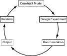
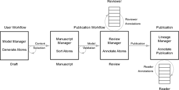
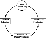
the four steps of the Publication Workflow (see Fig. 1). This specification covers
single cell models.
- User Workflow:
Selecting the “User Workflow” tab presents the User Workflow panel
that contains the following selectable menu items (see Fig. 2).
- Construct Model:
- Import Model:
Load and open a pre-existing project environment in the GUI.
Default: NDF format. Other loadable file formats include:
NeuroML, 9ML, or from a GENESIS 2 model imported via
the NS-SLI module.
- Create Model:
- Create single compartment model:
- Create compartment.
- Define passive membrane parameters.
- Create multi-compartment model:
- Import cell morphology.
- Define passive membrane parameters for soma and
dendrites. Default: Somatic and dendritic parameters
identical.
- Populate model:
- Add channel types from channel model library.
- Define
 for each channel type.
- Define 1-D distribution of channel densities for each channel
type included in multicompartment model. Choice
of:
- Uniform: Default for dendrites and soma. Can be
set independently for soma and dendrites.
- Gamma: Dendritic density defined by absolute
ortho- or antidromic distance from soma along single
dendrites.
- Modify model parameter values:
- Model summary:
Generate tables containing passive membrane properties and
channel, synaptic, and gap-junction parameter values (if
present).
- Save tables: Generated during model checking step of User
Workflow.
- Black: Default values.
- Green: User modified values.
- Red: Problematic values, e.g. out of expected range.
- Annotate tables:
- Explore model:
- Generate list of model compartments: Selecting one
or more compartments from this list generates a list of
properties, components, and parameter values for each
selected compartment.
- Selected compartments: Map to 3-D scalable and
rotatable cell morphology.
- Generate list of model components: Selecting a
model component generates a list of compartments
that contain the given component. Location of selected
components map to 3-D scalable and rotatable cell
morphology.
- Annotate model:
Record source of any changes made to published parameters (the
default parameter values of the model). This should include
whether the source is one of the following:
- Citation for published source of new values.
- Obtained from simulations.
- Save model: Choice of NDF, NeuroML or 9ML file formats.
Model can be saved in one or more formats. Default format:
NDF.
- Design Experiment:
- Choose inputs:
- Set stimulus type: One of:
- Current injection.
- Current clamp.
- Voltage clamp.
- Synaptic stimulation.
- Set specific parameter values of stimulus protocol:
- Current injection: Set magnitude and duration.
- Current clamp: Set magnitude and duration.
- Voltage clamp: Set holding potential and duration.
- Synaptic stimulation:
- Dendritic location.
- Number of synapses.
- Frequency.
- Temporal distribution of impulses: uniform, poisson,
gamma.
- Choose outputs:
- Select and set parameter values to be saved.
- Choose output resolution:
- Save experimental design: Automatically saved as part of
SSP file.
- Run Simulation:
- Set and check runtime options:
- Update time step duration: fixed or variable.
- Simulation duration.
- Visualize runtime parameters.
- Run simulation:
- Save model state: This can be used to eliminate time required
for model startup.
- Reset simulation: Set solver variables to values given by one
of:
- Default: Initial state of last model saved.
- Specified previously saved model state.
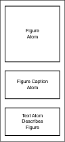
- Output:
- Construct draft atoms: For example see Fig. 3.
- Internally: Via g3plot and/or the Studio.
- Externally: Via Matlab, xmgrace, Mathematica, etc.
- Import externally generated figures, graphs and
tables:
- Check simulation output: Does expected output exist.
- Check validity of results: Does output make sense.
- Analyze output: Statistical analysis.
- Annotate draft atoms:.
- Iterators:
- Batch file construction:
- Manual: From text editor generate SSP file variants..
- Automated: Use scripts to automatically generate SSP
file variants.
- Dynamic Clamp: RTXI.
- Note: During completion of the User Workflow a numbered list is
constructed of all “Draft” atoms (see Fig. 4).
- Select Draft Atoms for inclusion in Manuscript: The
components of a project to be included in a publication are
selected from draft atoms generated during completion of the
User-Workflow. In the content selection step (following), these
atoms become ”Manuscript” atoms.
- Content Selection:
- Gather selected manuscript atoms:
- Organize selected manuscript atoms: The list of atoms
chosen by an investigator for publication can be ordered.
- Automated Model Validation:
Ensure lineage starting point of the model employed for simulations is a
previously published source model.
- Model verification: Performed on
- Morphology.
- Cable discretization.
- Equations for different membrane and synaptic channel types
and their kinetics.
- Model parameter values.
- Dynamic response to specific current injection and voltage
clamp protocols.
- Test robustness of parameter values: Assess fragility of new or
changed model parameters.
- Verify parameter values: Determine ‘normality of new or changed
parameters used by model.
- Check publication atoms: Numerical values cited in publication
atoms are compared with model values.
- Verify figures: Check all figures are generated by the same
model.
- Identify changes to base model: Compare project model to base
model.
- Check morphology.
- Check parameter values.
- Identify source of changed values: Are changed values from new
experimental data or simulations.
- Peer Review/Publication:
- Automated validation report: Provides technical summary.
- Morphology.
- Parameters.
- Equations.
- Figures.
- Tables.
- References.
- Human review:
- Narrative.
- Model.
- Model extensions.
- Novelty.
- Significance.